

When you need to reverse engineer a physical component, learning how to prepare part for 3D scanning is essential for success. 3D scanners collect millions of precision measurement points from surface geometry. However, physical contaminants, reflective coatings, and hidden internal features can severely distort optical data.
Consequently, proper surface preparation directly determines scan accuracy and downstream model quality. In addition, thoughtful preparation saves considerable time during scan-to-CAD conversion. This practical checklist guides engineers, designers, and business owners through every stage of preparation.
Why You Must Prepare Part for 3D Scanning Carefully
Optical and laser scanners rely on light reflections to capture physical geometry accurately. Therefore, any surface defect, grease layer, or glare will alter the measured points.
For example, a thin layer of cutting fluid can add unexpected thickness to critical tolerances. Similarly, highly polished metal surfaces scatter laser lines, creating missing data holes. In practice, preparing your component prevents measurement errors before scanning begins. Furthermore, completing key essential product preparations ensures your service provider receives clear reference information.
Step 1: Clean and Degrease the Surface
First, remove all dirt, oil, and surface residue from the object. Industrial parts often carry machining lubricants, shop grime, or rust preventatives. For instance, if you prepare part for 3D scanning without removing oil, the optical scanner will misinterpret surface details.
In addition, clean surfaces thoroughly using isopropyl alcohol or an appropriate mild solvent. However, avoid harsh chemicals that could damage delicate plastics or surface coatings. Next, dry the part completely using a lint-free microfiber cloth. In fact, even small dust particles can cause artificial bumps in high-resolution meshes.
Step 2: Handle Reflective, Dark, and Transparent Surfaces
Light-based 3D scanners struggle with three specific surface types: shiny metal, pitch-black plastic, and glass. For instance, glass allows light rays to pass directly through the component.
To solve this challenge, apply optical scanning matte sprays onto transparent or reflective areas. According to technical guidelines from organizations like NIST, temporary sublimating sprays evaporate completely without leaving residue behind. Consequently, you can treat sensitive parts without risking permanent contamination. On the other hand, permanent developer powder or chalk spray works well for non-critical rough components.
Step 3: Identify Critical Features and Mating Geometry
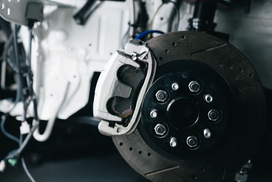
Not all features on a physical object carry equal functional importance. Therefore, you must identify mating faces, alignment pins, and tight-tolerance bores before scanning.
In addition, standard 3D scanning methods often struggle to capture internal screw threads or deep blind holes. When you prepare part for 3D scanning, note these critical dimensions manually with digital calipers. As a result, your CAD designer can recreate exact thread pitches during parametric modeling.
Step 4: Disassemble Complex Assemblies
If your object contains multiple interconnected components, consider complete disassembly. Scanners cannot capture hidden internal surfaces or obscured mechanical features while parts remain assembled.
For example, when recreating discontinued mechanical parts, scanning individual pieces yields far superior geometry. Furthermore, disassembling components allows the scanner to capture internal mounting bosses and alignment ribs. Meanwhile, take clear reference photos during teardown to record original mechanical relationships.
Step 5: Document Wear, Damage, and Manual Dimensions
Legacy components frequently exhibit surface wear, scratches, or manufacturing defects. However, a 3D scanner records exact current physical condition, including damage.
Therefore, document whether you need the final model to match current worn geometry or nominal design intent. In addition, record baseline physical dimensions with mechanical calipers or micrometer tools. Consequently, these manual measurements serve as vital validation checks during scan alignment.
Step 6: Choose File Formats Before You Prepare Part for 3D Scanning
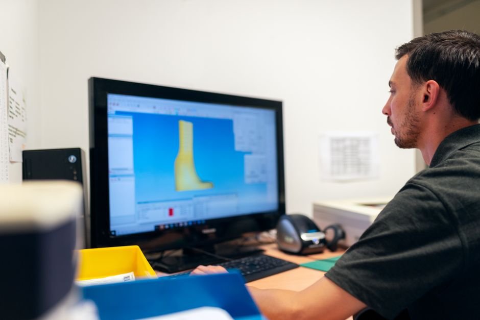
Before you prepare part for 3D scanning, determine your required digital file output. 3D scanners natively generate polygon mesh files such as STL or OBJ format.
However, mesh files consist of flat triangles rather than native CAD geometry. If you need editable feature trees, request conversion into parametric STEP or IGES files through custom CAD design services. In practice, defining file requirements early prevents unnecessary redesign work later.
Checklist to Prepare Part for 3D Scanning Projects
Before submitting your component for scanning, review this quick verification checklist:
- Clean all oil, grease, and dust from every visible surface.
- Apply temporary anti-glare spray to dark, shiny, or clear surfaces.
- Measure critical holes, threads, and tight tolerances with calipers.
- Disassemble multi-part hardware assemblies into individual pieces.
- Document original design specs, wear patterns, and broken features.
- Capture high-resolution photos of the part from multiple angles.
- Specify whether you need raw STL meshes or parametric CAD files.
Getting Started with Reverse Engineering
Preparing your physical components properly guarantees better measurement data and smoother CAD conversion. Ultimately, thorough physical preparation saves hours of manual engineering work.
If you are ready to convert physical hardware into digital CAD models, you can submit a project request to connect with independent makers on 3DGigs.