

Preparing digital designs for physical production requires selecting the proper file export. Evaluating STL vs STEP files is a critical step for creators, engineers, and product designers. Selecting the right format depends heavily on your specific production method and software workflow.
Both formats serve vital roles in modern digital manufacturing workflows. However, they store geometric data in fundamentally different ways. Understanding these core structural differences ensures smooth communication with independent manufacturing partners.
Understanding Geometry: Triangulated Mesh vs CAD Geometry
An STL file represents a 3D object as a triangulated mesh surface. Specifically, the file covers the outer shell of a model using tiny planar triangles. As a result, curved surfaces become collections of flat facets rather than true mathematical curves. Higher resolution exports add more triangles to smooth out curves. However, this adjustment also increases file size significantly.
In contrast, a STEP file uses boundary representation to define exact solid surfaces. This mathematical approach represents curves, cylinders, and complex organic shapes precisely. Consequently, a STEP file maintains true geometric accuracy regardless of display scaling. In addition, the format retains solid mass attributes essential for engineering analysis.
Workflows and Tooling Across Manufacturing
3D printing slicers rely heavily on mesh inputs like STL files. Slicing software converts surface meshes into linear movement commands for additive hardware. Therefore, STL remains a standard export format for quick 3D-printed prototypes. Most desktop slicers read triangulated meshes quickly and reliably.
On the other hand, parametric CAD tools and CNC machining software require exact geometric boundaries. Professional computer-aided manufacturing tools rely on standard exchange formats like the ISO 10303 STEP standard. For example, machinist software uses exact solid edges to calculate precise tool paths. Similarly, injection molding tooling design demands exact surface boundaries rather than faceted meshes.
Gains, Losses, and Conversion Realities in STL vs STEP
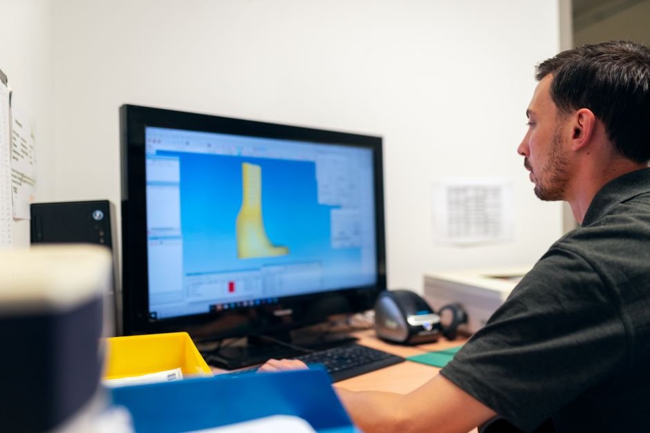
Many beginners assume converting file types is simple. However, converting an STL mesh into a STEP solid involves major technical trade-offs. Converting a STEP solid into an STL mesh is straightforward because CAD software easily calculates flat surface triangles from solid bodies.
Conversely, converting an STL mesh into an editable STEP solid is difficult. Automated translation utilities merely wrap flat mesh facets inside a STEP file container. Consequently, this conversion process does not recreate an editable CAD solid. Instead, modifying the geometry usually requires manual surface reconstruction by an experienced CAD designer. Professional custom CAD design services can rebuild raw mesh files into functional solid models.
Feature History Clarity in STEP File 3D Modeling
Engineers frequently share STEP files across different design software platforms. Fortunately, STEP files preserve exact solid geometry between distinct CAD tools. However, readers must understand one critical limitation regarding feature history.
A STEP export does not retain the original parametric feature tree. For instance, sketches, extrusions, and hole wizards from programs like SolidWorks or Fusion 360 do not transfer over. Instead, the receiving software imports the design as a static solid body. Designers can still modify solid faces directly. Nevertheless, they cannot simply double-click an old feature to alter its early sketch parameters.
Comparing STL vs STEP for Manufacturing
When evaluating STL vs STEP options, each format serves a distinct operational purpose. Review this practical summary table to compare key characteristics:
| Feature Category | STL File Format | STEP File Format |
|---|---|---|
| Geometry Representation | Triangulated mesh surface approximation | Exact mathematical solid and surface B-Rep geometry |
| Typical Uses | 3D printing slicers, rapid visual mesh prototypes | CAD modeling, CNC machining, injection molding tooling |
| Editing Considerations | Difficult to modify parametric dimensions directly | Fully editable solid geometry across CAD platforms |
| Manufacturing Handoff | Requires resolution tuning to avoid visible mesh facets | Preserves exact dimensions, curves, and edge boundaries |
| Format Limitations | No internal solid mass data or native units stored | Does not transfer parametric sketch feature history tree |
Choice Factors and Technical Communication
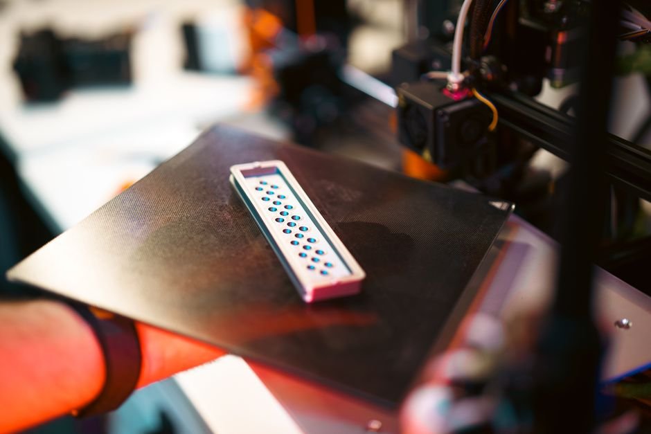
Choosing between these formats depends on your downstream manufacturing process. If you only need a quick 3D-printed visual prototype, an STL file is often sufficient. However, if your project requires CNC milling, sheet metal bending, or injection molding, a STEP file is necessary.
Furthermore, sending a 3D file alone is rarely enough for custom fabrication. File formats store geometry, but they do not automatically communicate full manufacturing intent. For instance, STL files do not inherently define physical units. Therefore, a model designed in millimeters might import as inches in a different program.
In addition, critical details like tight tolerances, thread specs, surface finishes, and material selections must be specified explicitly. Clearly communicating these requirements prevents costly fabrication errors. Understanding how 3DGigs works helps creators coordinate these deliverables effectively with makers.
Hypothetical Example: Designing a Custom Plastic Enclosure
Consider a hypothetical scenario featuring an entrepreneur developing a custom electronics enclosure. During early product testing, the creator needs a quick physical model to verify internal component spacing.
First, the designer exports an STL file from CAD software. The creator sends this mesh file to a 3D printing maker to produce an affordable initial prototype. This initial print reveals that a circuit board mounting post needs a minor dimensional shift.
Next, the entrepreneur needs to update the underlying CAD model. Because mesh editing is limited, the designer modifies the native CAD solid and exports an updated STEP file. The creator then supplies this solid STEP file to a maker for precision CNC machining or tooling design. As a result, the project moves seamlessly from rapid prototyping to production-ready manufacturing.
Pre-Submission Customer Checklist
Before requesting custom design or manufacturing services, prepare your project assets carefully. Reviewing essential preparations before hiring a 3D modeler speeds up project discussions. Use this practical checklist prior to project submission:
- Identify the primary process: Determine if your part will be 3D printed, CNC machined, or molded.
- Select the correct file format: Provide STEP files for engineering parts or STL files for basic 3D printing.
- Confirm units and scale: State whether your model uses millimeters or inches explicitly.
- Specify material requirements: List desired plastics, metals, or mechanical properties.
- Define critical dimensions and tolerances: Highlight mating parts or tight hole dimensions.
Start Your Next Custom Manufacturing Project
Choosing the right file format ensures your custom parts move from design to physical reality without unnecessary delays. Whether you need initial file preparation or solid CAD modeling, working with independent makers helps bring your concepts to life.
Ready to move your custom design forward? Visit 3DGigs to connect with skilled makers for 3D modeling, prototyping, and fabrication. You can Start a Project on 3DGigs today to discuss your specific project requirements.